In my last post, I described how I duplicated a special Volvo puller for removing a cam gear. As the disassembly and refresh of Beck's engine continued, I needed a couple of other special tools. Here's how I made them:
The first tool is a "lifter puller." Deep within the engine, there are lifters that ride up and down on the camshaft, as part of the mechanism that opens and closes the valves. They are precisely sized to the hole they ride in, and over decades of use, a hard layer of shellac builds up on the lower part of the lifter, making it difficult to extract them from the hole. In a full engine rebuild, you just push them out the bottom, but when just doing the top end, you have to overcome that resistance.
The problem is made worse by the minimal clearance to get to the lifters, especially on the first and last ones:
I tried every pair of long pliers I owned, and none of them would adequately grab the lifter. Then I got the idea of modifying these Harbor Freight hose pliers. In the right photo, you can see how I got out the torch and increased the bend to 90 degrees. That allowed me to grab the lifters securely, but the shellac was just too thick - I still couldn't pull them out. But I was happy to have those modified pliers, because they did work to pull the lifter as far as it would go in the bore, making my eventual solution easier.
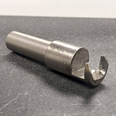
That eventual solution was a puller to be used in conjunction with a small slide hammer, to tap the lifters out of the bore. My friend Jake told me about that one - there was a factory tool to do it in the Ford 427 engines he used to regularly rebuild. I made a prototype, and then confidently made the tool in steel. It broke on the second lifter. The one pictured below didn't break! This photo shows a lifter snagged in the tool.
Here's the tool showing the "business end." The back side is tapped M10-1.50, to match my Chinese slide hammer. The shaft is turned down to allow it to tilt into place on those tight clearances on #1 and #8.
The drawing was of the first try, and you can see that I made the ears too thin the first time. But I corrected the numbers, so you can make your own. Just make it look like the picture, using the numbers in the drawing.
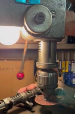
Once I had the lifters out, I turned my attention to refacing the rocker arms, which wear over time. The curved surface that opens the valves can eventually wear a groove, but mine were not that bad. Jake was instrumental in this project too, because he sent me a video (still photo below) of how he refaced them in his drill press using first a 3" grinding wheel, and then a cut-off disc in an arbor.
Well, I couldn't do it quite that way. In the first place, my drill press is smaller, so I couldn't leave the rocker arms on the shaft. Also, I didn't have a 3" grinding wheel with arbor, and neither did Harbor Freight. But they did have something I was itching to try anyway - "twist-lock" 3" abrasive discs with a matching mandrel. Only $16 for the kit.
The only problem is that the mandrel is made of rubber - too wobbly for the task at hand. I needed a solid mandrel for the disks. So... I cut out the good part! In this photo, you can see the screw thread on the back of the sanding disc, and the matching receiver in the knurled center of the mandrel. The back side of that knurled piece is tapped for the screw-in shaft.
I started making my own mandrel using a 3" aluminum scrap I had gotten from my friend Phil. I started on the lathe, parting it about 1" thick, and after I got pretty deep, I held it in a 16" pair of Channel Lock pliers and finished cutting at the band saw.
Back to the lathe, where I faced both surfaces, and then drilled and bored the center to be the exact size I needed for that press-in mandrel center that I cut out of the rubber mandrel.
Jake had gifted me this cute little set of snap gages, and they worked great to keep up with my progress in boring that hole!
Once the boring was done, I used the 20 ton press to insert the center into my new mandrel.
Once I had the back side pressed all the way in, I installed the shaft, and returned to the lathe to true up the face. I reduced the thickness until I had about 0.050" depth from the face to the screw receiver for the twist-lock. Then I bored a recess, for clearance of the plastic disc in the center of the abrasive discs.
And voila! The abrasive twists on easily, and sits flat on the mandrel.
I also made a little brass shaft, sized to be a good sliding fit on the rocker arm, and cobbled up a way to hold it in position on my drill press. You can see the mandrel is already in the chuck also.
It might be hard to visualize this process, so I made a video showing how it works. If you can't see the video in this post, try this link: https://youtu.be/RyFiz3cfW8E
And here's the before-and-after! The right hand picture is after a few passes at 240 grit. After that, I used the green abrasive pad (also part of the kit) to polish a bit more, and then a felt wheel with polishing compound to get it even better.
Of course, I could have bought something instead of all of that effort, but... I just like to make tools!


you never STOP AMAZING ME WITH YOUR CLEVER . SKILLS ... KEEP THESE COMING... aLLEN
ReplyDeleteNice work Emery, I'm following along. I seem to recall some rocker arms are not flat on the business end which complicates things, maybe the VW's.
ReplyDelete