
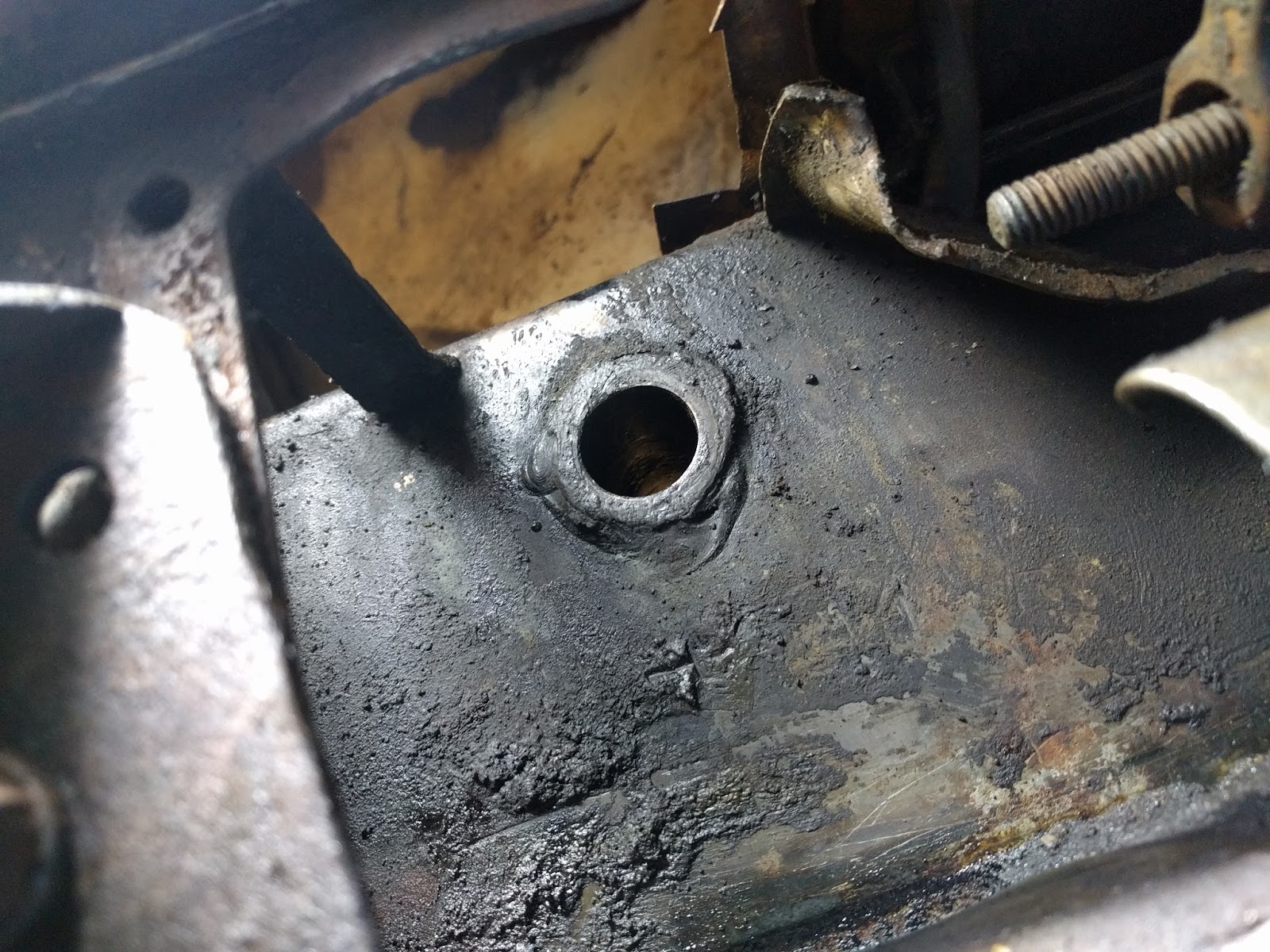
The issue is that there's almost no clearance around those bushings. Here's a photo of the inner bushing in the frame rail, taken from below through the only hole that gives access. The outer bushing has even less access, due to the proximity to the fender trim panel:
In my prior post, I also referenced a great article by Jeffrey Delk, who assured the reader that while it is much easier to replace the bushings during a restoration with the body and transmission out of the way, it was definitely possible to remove those bushings without having to do that. I decided to try a technique that worked for me previously - using an homemade internal expanding collet.
This photo of a collet inside the new bushing shows how it works. The collet is sized to fit closely in the bushing, and there are four slits that allow it to expand tight against the bushing's inside wall. In this first version I made, the expansion happens from behind by tightening a bolt into the cavity in the collet:

Well, I made two different tries in that style, and it just wouldn't tighten enough to keep from slipping. So, I tried another style. In this one, backing a bolt out of the collet pulls a cone-shaped nose piece into the collet, expanding it:

That didn't work either. As I was designing a third style of collet, I realized it couldn't work either because there wasn't enough clearance behind the bushing inside the frame. Time for another approach, and this photo has all the components of what I came up with:

Basically, I decided to remove both bushings at once by pulling them both through the frame rail on the side with more clearance. The key to this technique is the custom mandrel that fits into the bushing, and has a shoulder that is exactly the right size to push on the bushing without getting stuck in the housing in the frame. Here's another look at that mandrel inserted into a new bushing. The mandrel is threaded through for a substantial 3/8-16 rod, allowing for plenty of pulling force:

My big fear was that trying to move them both at once would get them jammed in the rail, and then I really would be looking at removing the body and transmission! But it worked great - I assembled the threaded rod into the mandrel placed in the outer bushing, and then put the pipe over the rod and inner hole, and tightened a nut on the heavy push plate until it pulled everything out into the pipe. Here's the victory photo with both bushings still on the fixture:

The same mandrel could also be used to insert the new bushings. Here's the setup for that - the only additional part is the big washer that establishes a shoulder so that it stops when the bushing is fully seated.

To make sure that the bushing started correctly, I ground a slight chamfer on each one:

Here's the setup on the frame rail, just ready to pull the outer bushing into the frame - you can see the wrench used to tighten the nut on the threaded rod to do the pulling:

Once both bushings were in place, it was time to test. If the old shaft wouldn't fit back in, then something was crooked. But it slid right in - success!
After that, the third bushing in the brake pedal was trivial to press out on the bench:

Some paint and pressing the new bushing in makes it good as new!

So that's the "worst job" done, but there's still a major bit of fabrication left to tackle. In Part 1 of the brake saga, I included this picture of the old shaft:

That crazy stack of washers is how the long-ago builder aligned the push rod for the Volvo clutch master cylinder. The long cantilever puts a big twist on the arm, and that's why it has the ugly weld that still didn't fix the crack that's opening up again. My plan was to make a longer shaft and support it with a bearing on the inside to allow better alignment for a long life.
But, of course, there's a problem. Access is so tight, there's a definite limit to how long a shaft I can fit in there. This afternoon I really got my exercise, moving from the the lathe to underneath the car, up and down, back and forth, as I shortened a test shaft 0.10" inch at a time until it would just slip though the available space. Then I compared:

Still about 5/8" short. Deep sigh... Here are my options:
1. Make the new shaft as long as it can be, and still use a spacer at the other end of the arm. The cantilever would be shorter, and if I made the arm thicker, it would resist cracking better.
2. Make the arm removable instead of welded-on, and drill a hole in the lower fender trim to allow a long shaft to slip in from the back. It's in a hidden spot, so that's a decent option. The challenge would be to design a long-lasting removable arm. The best case for that would be a splined joint on the shaft and a matching splined socket in the arm. Those are hard to make.
3. Remove the transmission and insert the correctly-sized shaft from the inside. It's not that hard to get the trans out, and it would give me the chance to check the health of the clutch while in there. It would also give me the option of finding and installing an overdrive trans, which would be cool.
4. Just buy a stock shaft and arm for $115 plus shipping, and duplicate this setup, and watch it to see how long it works before cracking. If I did that, I'd still modify the shaft according to Delk's article for improved lubrication of the three bushings.
I'll let you know what I decide in the next post! Feel free to give your vote in the comments.
I vote for trying to make it first, then if that fails throw some $ at it
ReplyDelete