

That rod is 1/2" in diameter, but you can actually feel it flex with light pressure on the unsupported end. Jake said that the standard way to support the far end is with a specific, heavy milling tailstock, but he noted that he more often would support it with a machinist's jack with a V-groove in the face that supports the stock.
In that post about the spin indexer, there was actually a photo of a machinist's jack, repeated below with the jack circled. That one is a rudimentary shop-made affair - just a bolt threaded into a scrap of aluminum. You thread the bolt in or out to make it fit exactly on what you want to support.

Because I set up the spin indexer to be mounted in the milling vise, I needed a very specific jack - one that could support work around 9" above the mill table. I resolved to make one, and started looking through the scrap collection for likely materials. I found a cast iron base that seemed a very good start:

I had rescued that base from the dumpster at Thaddeus Stevens School of Technology, and I hasten to add that the "dumpster dive" was authorized! Last summer, the machine shop at Stevens moved to a new location, and they threw out a lot of odds and ends. The head of the machine shop invited several members of Make717 to come look for treasures, and I found several. In fact, this 4" long steel scrap came from the same dive, and it was a good enough fit for the base:

I don't know what alloy that steel is, but I know it's hard! Here's an early stage of lots and lots of drilling. I drilled all the way through, and tapped the first inch or so 5/8-11, and then drilled the rest of the length for clearance.

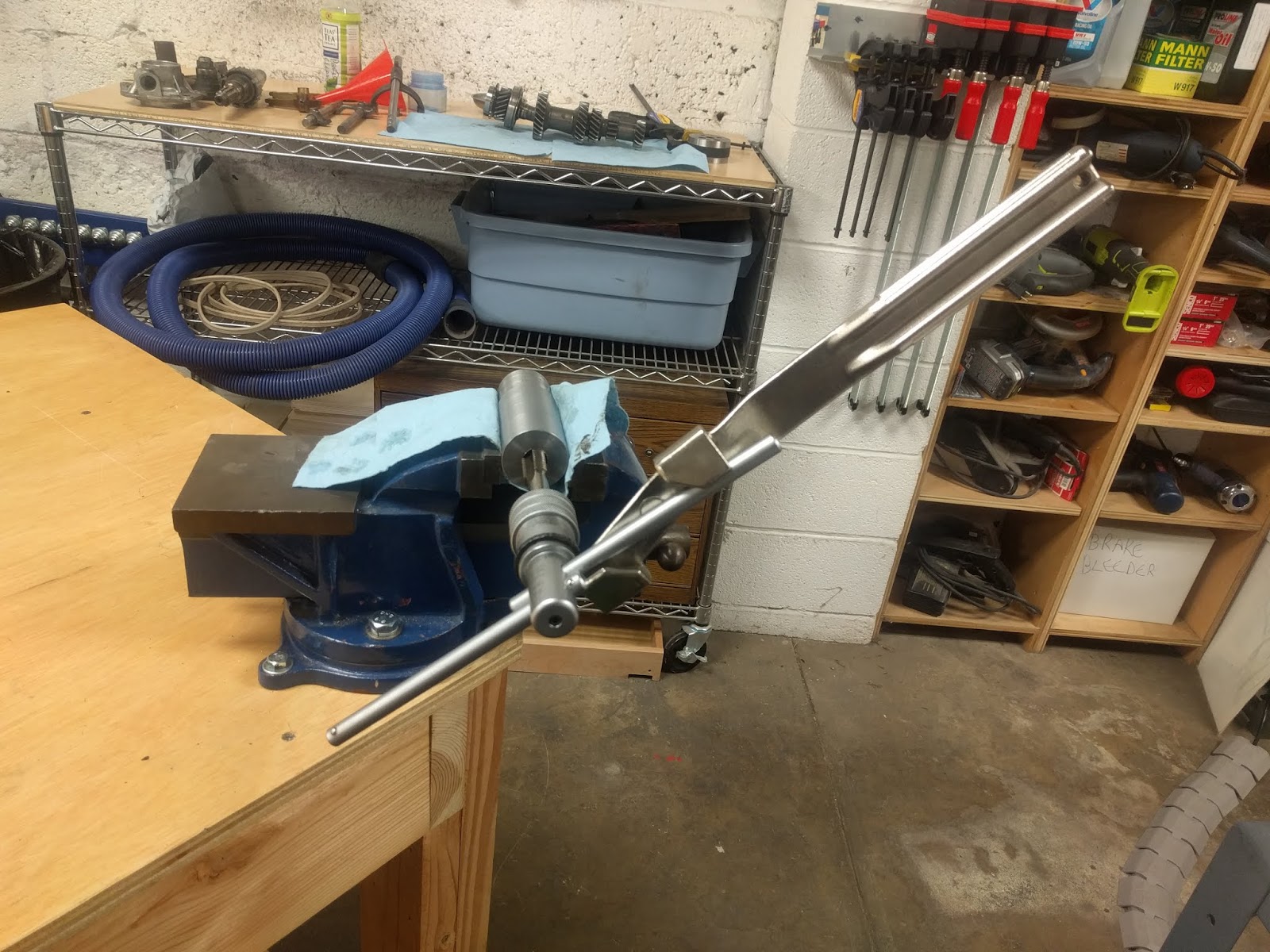
I usually tap holes like that in the lathe, because it helps keep things straight. However, the combination of hard steel and a dull hand-me-down tap defeated me, and I wound up using a handle with an extension bar:
It worked, but inevitably the threaded hole was not perfectly straight doing it by hand. Not a real problem on this low-tech implement, but it did mean even more drilling to increase the size of the clearance hole.
The original plan was to use scrap threaded rod for the jack shaft, but then I would have had to create a head for it. I relented on my "scrap only" rule and bought a couple of 5/8-11 bolts. I wanted to try a technique I had heard about: hold the work piece in the mill vise at a 45 degree angle, and then use the corner of an end mill to cut the V in the face. I used my digital angle gauge to set my ER32 collet block in the vise:

I really, really wanted it to say exactly 45.00 degrees for the photo, but after a lot of fussing with it, I settled for 44.95 instead. Plenty close enough. I used the lathe to flatten the head of the large screw, put it in the collet, and aligned the end mill with the center. I then proceeded to ruin a couple of bolts as I tried to cut the V.
Finally I realized the trigonometry of the situation. I'm cutting a face that is set at 45 degrees. Thus, I need to move the cutter both down and toward the cutter the exact same amount. Here's the technique I settled on, which worked very well.
First, I used an indicator to set the top "flat" of the hex to be level, which also made the points across the center level:

Then, I carefully aligned the corner of the cutter to the center of the bolt, using the pattern left from the lathe when I flattened it. It takes moving all three axes to get it right, and once it's as good as you can get it, zero the X and Z axis DROs or handwheels.

Move the cutter away from the bolt, and move X (toward the cutter) and Z (down) exactly the same amount. I chose 0.005" for that initial mark. It looked pretty good, so I started milling. The interesting thing I realized is that it's easy to "fudge" the alignment by varying Z and Z slightly. Once the V was established, I could see that I was slightly off the point. I moved X a few thousandths more than Z to make it better. After several passes, I had a pretty good V:

Now we're getting somewhere! I carefully aligned the base in the mill vise, and drilled and tapped 1/4-20 for a set screw for the center support:

More rummaging yielded a brass knurled nut I made some time or another, and I used red Loctite to permanently insert a 1/4-20 socket head cap screw to make an instant knurled knob:

And here's the finished product in action! One tab of the base is bolted to a t-nut in the mill table to hold that in place.

I guess I'd better come up with some spin indexer projects to put all this wonderfulness to use...

A 5/8-11 tap requires a lot of torque and I'm not surprised to see you doing it with that big T wrench. A trick, drill the hole partway for 25% threads to start, then finish with 50-75%
ReplyDelete