
Getting that trans apart was a long, hard trial, because it was a rusty mess inside. Here was my first view:

See the two components circled? Those are tabs that are the actual subject of this post. More in a minute, but first let's get these shafts out of there. I didn't want to pull that rusty mess out through the reamed holes in the back of the transmission case, so I attacked them with an air-powered cutting wheel:

That allowed me to put the unrusted part out the back, and then work the rusty bits out inside the case. Once done, I had a pile of rusty pieces, but the important sliding pieces came off without damage after some cleanup.

Most of the components in this case were too rusty to reuse, but I was gratified to find that the unique tabs and main shaft were OK. I had another used trans to steal parts from (I had thought it was too worn to rebuild, but once I saw this mess I realized it wasn't so bad after all!), but there was one problem:

The shaft in the front is from the M41 trans, and the second hole is to locate one of the tabs. It's really important for it to be there, because that tab actuates the switch that only allows the overdrive to engage in fourth gear. If you ever engage an overdrive while the trans is in reverse, it immediately destroys something called the "anti-rotation clutch" in the overdrive unit, so you really have to have that interlock switch. I just needed to put that hole in the right place in the second shaft in the picture, which is from my pile of parts from the M40 spare.
I started by making a little alignment tool that more-or-less precisely fits the existing holes.

I say "more-or-less" because those holes were worn after all these years, and every one I tried to measure was a little different. I used the tool to align one of the cut off stubs, and experimented until I had a setup that made a hole that did a good job of engaging the grub screw for the tabs. Then I mounted the cut-off piece with two holes, aligned it carefully, and then used the mill readout to determine how far away the second hole was. The answer was 1.053". Sort of an odd number, but I did the test twice and got the same answer both times, so that's what I used.
I made several test pieces to nail down the procedure, and then used the alignment tool to locate the shaft from the M40 trans:
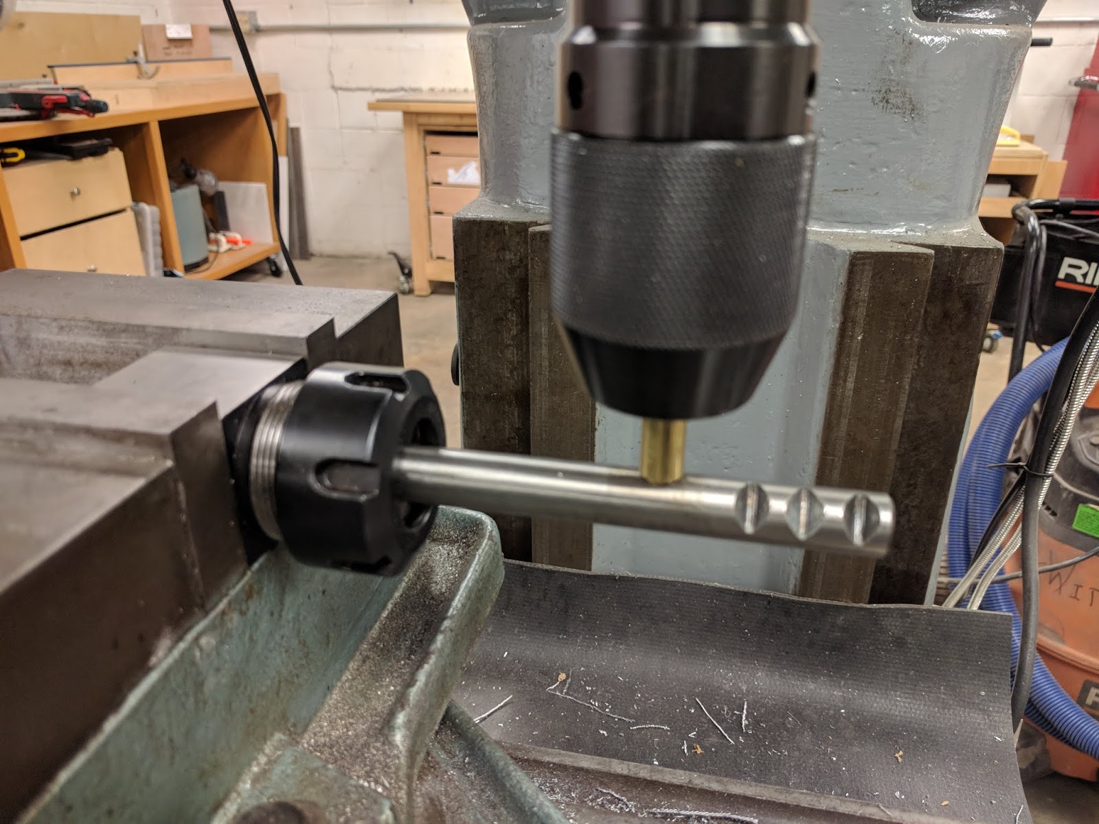
It's sticking out so far because I'll move down the shaft toward the vise to drill the second hole. Here's the step-by-step, in case I ever need to do it again:
1. Align to first hole, and move X-axis 1.053" inches down the shaft.
2. Center-drill
3. Drill 7/32" to a depth of 0.300".
4. Switch to a 5/16" countersink, and zero the depth indicator against an undrilled spot on the shaft.
5. Realign to zero so the countersink is directly over the hole.
6. Countersink to 0.150" on the depth indicator.
When done, I had a matching hole:

And this is what the assembly looks like .Of course, I have to disassemble it to get it back into the trans, and I won't know if my alignment was perfect until I can test the engagement of the switch.

And now for the reason I decided to post this: I need help from my machinist buddies! This shaft was the easy one, because I had an existing hole to index from. On the other shaft, there's a tab for the reverse light switch. In the M40, that switch is at the back of the case, but it had to move to make room for the overdrive unit in the M41. Anyway, that shaft only has one hole, which means my M40 spare has no holes at all.

Continue on to Part 52...
No comments:
Post a Comment