
Jake and I agreed to jointly write a procedure to convert from the ancient generator technology to a modern alternator, specific to the world of MG cars with Volvo engines. This is one of those collaborations that has only become possible with the Internet, because Jake lives in sight of the Pacific Ocean, and I live a couple of hours from the Atlantic! There's a lot to consider, and much of it is pretty technical. So.... my first caution is, don't start until you understand every step and implication of the process! Here's a photo collage of both conversions, Jake's to the left, and mine to the right:

While they look similar, they are actually rather different in ways that will be explored below. Let's start with all the decisions you need to make:
DECISION POINTS
1. Volvo engine blocks have two different systems for mounting the generator/alternator, based on year. As it happens, Beck's old engine was the older version, and the newer B18 engine I'm working to install is the newer. This photo makes it clear - see the extra threaded hole in the lower picture? B18's starting in 1967, and all B20's have that, and it it specifically there to mount an alternator. It is tapped 7/16-14 UNC.

2. This post is specifically about so-called "internal regulator" alternators. If you want to use the older external regulator for some reason, see #3 below under RESOURCES for help with that.
3. You need to choose between "one-wire" and "three-wire" alternators. The one-wire alternator is super easy to install, the three-wire allows you to have a dashboard indicator to alert you to alternator problems. Jake and I both opted for three-wire, and that's what will be discussed in this post.
4. Even with buying all-Volvo parts, you will probably need to do a bit of fabrication, or at least carefully stack washers to do some necessary spacing. Do you feel up for it?
5. Maybe this should be first: you MUST convert to negative ground if you are running a positive ground MG (which includes the TC, TD and TF). See Part 18 of this blog for details.
The rest of the post will basically expand on all this, so if you are interested, here are a few resources that I urge you use to deepen your knowledge and understanding:
RESOURCES
1. Moss Motors has an excellent 14-minute video on the difference between a generator and alternator, and how to convert to an alternator: https://youtu.be/4NsAYiUHsho
2. Grassroots Motorsports has a fine article on fabricating an alternator bracket:
3. The Volvo parts supplier IPD sells a bracket that is perfect for use with older Volvo blocks at this link: https://www.ipdusa.com/products/6910/112993-volvo-alternator-bracket-kit-ipd-112993
If you click "Product Information" about halfway down that page, you can see a pdf file that you can download with more info, and in particular, instructions for using the Volvo regulator if you want to use an external regulator. NOTE THAT THE MG REGULATOR WILL DEFINITELY NOT WORK!
CHOOSING AND MOUNTING THE ALTERNATOR
Jake chose to use a Yanmar alternator that he already owned. It is a 30-amp alternator, and uses the older mounting scheme with two tabs at the bottom. Thus, even though he has the newer block with the mounting hole in place, he needed to fabricate a mount specifically for that alternator. Here's a photo:

You can click this photo to expand it. Notice how Jake carefully added two tabs to mount the alternator, and then carefully located the three mounting holes so that the alternator is perfectly aligned with the drive pulley on the engine.
In my case, I bought a Volvo alternator from eBay and thought I was good to go. More about that in a minute, but first... wherever you buy the alternator, you'll probably need to buy a pulley separately. Here are the specs of the pulley I bought:
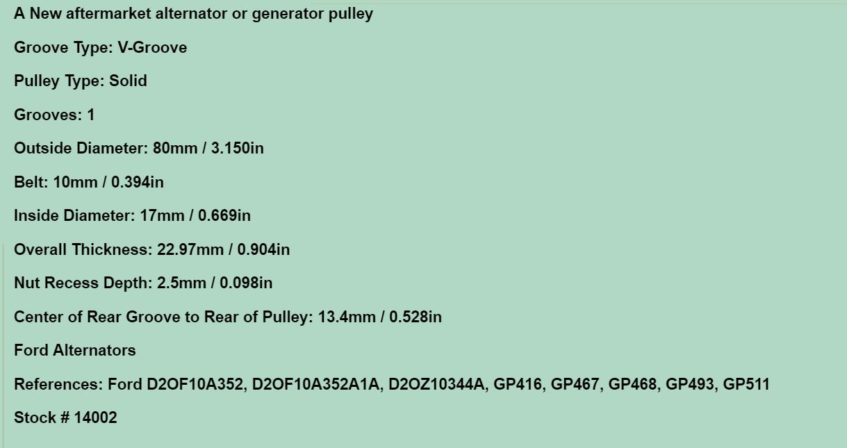
By far the most important measurement is the Inside Diameter, because that's what matches the shaft on the alternator. I had measured the alternator I bought, and found it to be 17mm - you should expect any modern part to have metric measurements. The Outside Diameter should be around 3 inches, and the Belt width should be 10mm or 13/32" to match the other pulleys on the engine. Don't worry if the pulley doesn't have a slot for a key, even if the alternator has one. Jake assures me that it won't slip if you hammer it on with a good impact wrench.
Now for the other, very important bit of advice I have about buying an alternator: buy it locally from a place where you can return it and try again! I didn't do that, and wound up having to do some significant modification that could have been avoided.
The important things I learned are:
1. The mounting hole at the bottom should be sized for a 7/16" bolt.
2. The mounting hole at the top (for the adjustment bracket) should be 5/16".
3. The thickness of the flange at the bottom should be 1" (one inch).
I believe that matching these specifications will give an alternator that will bolt up and align with the pulleys. You may still need to shim the adjustment bracket on one side or the other, but that's easy.
In my case, I bought a Volvo alternator that matched points 1 and 2, but had a mounting flange closer to 2" thick. This photo shows the result - the ruler shows the desired belt path, and you can see where the alternator pulley wound up!

By the time I realized that, substantial time had passed and I had installed the pulley multiple times, so I didn't feel I could return it. The electrons don't care which way the alternator is mounted, so I mounted it "upside down." This photo collage shows the steps - I drilled out the old mount (top left), pressed in a custom bushing made on my lathe to match a 7/16" bolt (top right), and modified the bracket to use a 7/16" bolt instead of 5/16", since I had just moved the original 7/16" hole to the top (bottom photo):

Then I could make custom spacers, bottom and top, to make everything align perfectly:
I sure hope that series of photos convinces you to buy the alternator locally from a place where you can return it and try again!
CHOOSING THE ALTERNATOR BELT
This was some great info I learned from Jake about how to specify a belt. He sent a whole chart about it, but here's the pertinent line:

We definitely need a 38 degree automotive Vee belt, and to match the stock Volvo pulleys it needs to be 13/32" wide. Nowadays belts are all metric, and 10mm is the closest match. The fine print in the chart tells you how to create a standard number for any belt. I believe the standard Volvo belt is a 13345, and that should work if you are using the stock exhaust manifold. As you can see in the opening photo, Jake is running a tubular header on his engine and that required a different belt for clearance.
Jake's passion for quality and reliability has led him to do extensive research on belts, and he believes that the "Gates Green Stripe" belts are the best choice for longevity. The Gates/Carquest belts that are available at Pep Boys and the like are not the same quality and will fail much more quickly. Jake said you'll need to order the Green Stripe belts, most likely.
WIRING THE SYSTEM
Internally regulated alternators are simple to wire, whether you opt for one-wire or three wire. Basically:
1. Run a BIG wire from the alternator B+ terminal right to the big terminal on the starter, the one that also is hooked to the battery. If you wish to continue to use the ammeter that is stock on early MGs, you may as long as your alternator won't overwhelm it. That's why Jake used a 30-amp alternator. Higher-amperage alternators (which is most of them) can be "shunted" to limit the current to the 30-amp max of the gauge - see http://www.deltecco.com/resources.html for more info.
2. If you want an indicator light, the easy way is to use a regular light bulb because current must flow "both ways" for the indicator/exciter circuit in the alternator. Since I'll be using an LED (already installed) I'll be using a shunt resistor for that circuit also.
The wire size can be figured from this excerpt from a chart Jake sent. I was surprised that the wire gauges were much smaller than I expected. If your current needs are under 5 amps, 18 gauge wire will do for any reasonable wire length in a car. If your needs exceed 50 amps, then you need more help than this blog can provide!

Having said that, there are possible bad consequences for going too small, and no negatives for going larger, so I typically go up a gauge or two. I will use 10-gauge wire for the short circuit from the alternator B+ terminal to the starter.
Here's a photo of the back of my alternator with the terminals labelled:

As noted earlier, B+ goes to the battery via the starter. D+ is the "exciter" wire that also drives the indicator light, and is omitted on a one-wire alternator. W can be ignored - it appears to be a tachometer signal for engines without spark plugs, like diesels. Finally, the B- terminal can be hooked to a good ground source. I'm using one of the old alternator mounting screws.
It's typical for Volvo/TD owners to want to keep a stock look as much as possible, and Jake went down that path too. He used the old external regulator as a connection point by cutting and bridging connections internally. Here's a photo, with his knife blade pointing to one of two cut traces. The wires at the left are cut also, and then the three rightmost terminals are bridged together with wire and solder, and the leftmost two are bridged also. Note that when the regulator is flipped over to mount, left and right are reversed so that the three leftmost terminals are bridged, and the two rightmost. Also, it is very important to unhook all the ground wires that are attached to the rightmost terminal (labelled "E") from the stock setup. You'll need to re-ground them elsewhere.

Here's what that's all about. Look at this screen shot from the Moss video. The three lines marked with green dots are bridged together on the three leftmost terminals, and the two unmarked wires are bridged on the right two terminals.

And here's a photo of Jake's finished installation with wires attached:

In Beck TD's case, it is already so modified that I was comfortable simply removing the old regulator and fuse box, and doing some rewiring. In fact, I got a bad case of "while-I'm-in-there-itis." My original plan was to replace just the ammeter gauge wiring and convert to a voltmeter, but one thing led to another and pretty soon every wire under the dash was unhooked and the dash was on the bench...

All that will be the topic of my next post, but for now I'll thank Jake for all his help, and include other things I learned from him in the course of this project:
1. If a car is front-engined and rear drive, the engine rotation is always clockwise as viewed from the front. That is, the fan should turn clockwise. I got confused about this because I had been researching on marine sites, and boat engines can easily turn the other way! Rear engined cars, likewise.
2. On the B18 and B20 Volvo engines, the distributor rotates counter-clockwise as viewed from the top. However, on the B16 engine it rotates clockwise.
Here are three diagrams that Jake said he uses constantly when working on Volvo engines. I'll probably print and post them at the Grant St. Garage also!


No comments:
Post a Comment