At the end of
Part 38, I concluded with this photo, showing how Troy Nace and I had removed Beck's head to see why the engine had low compression and heavy oil consumption. What we found wasn't pretty - severe damage to the cylinder walls. The engine will have to come out for rebuilding.
However, there was another problem I uncovered while rebuilding the carbs, and I wanted to get straightened out before removing the engine. I had discovered that my throttle was only opening around a quarter of the way! I sent these two photos with captions to the
Volvo Engined MG internet group to ask for opinions:
Others sent pictures of their linkage, and I could see that mine was crude and binding by comparison. An excerpt from that first picture makes it clear how the vertical arm was at an odd angle and in danger of binding.
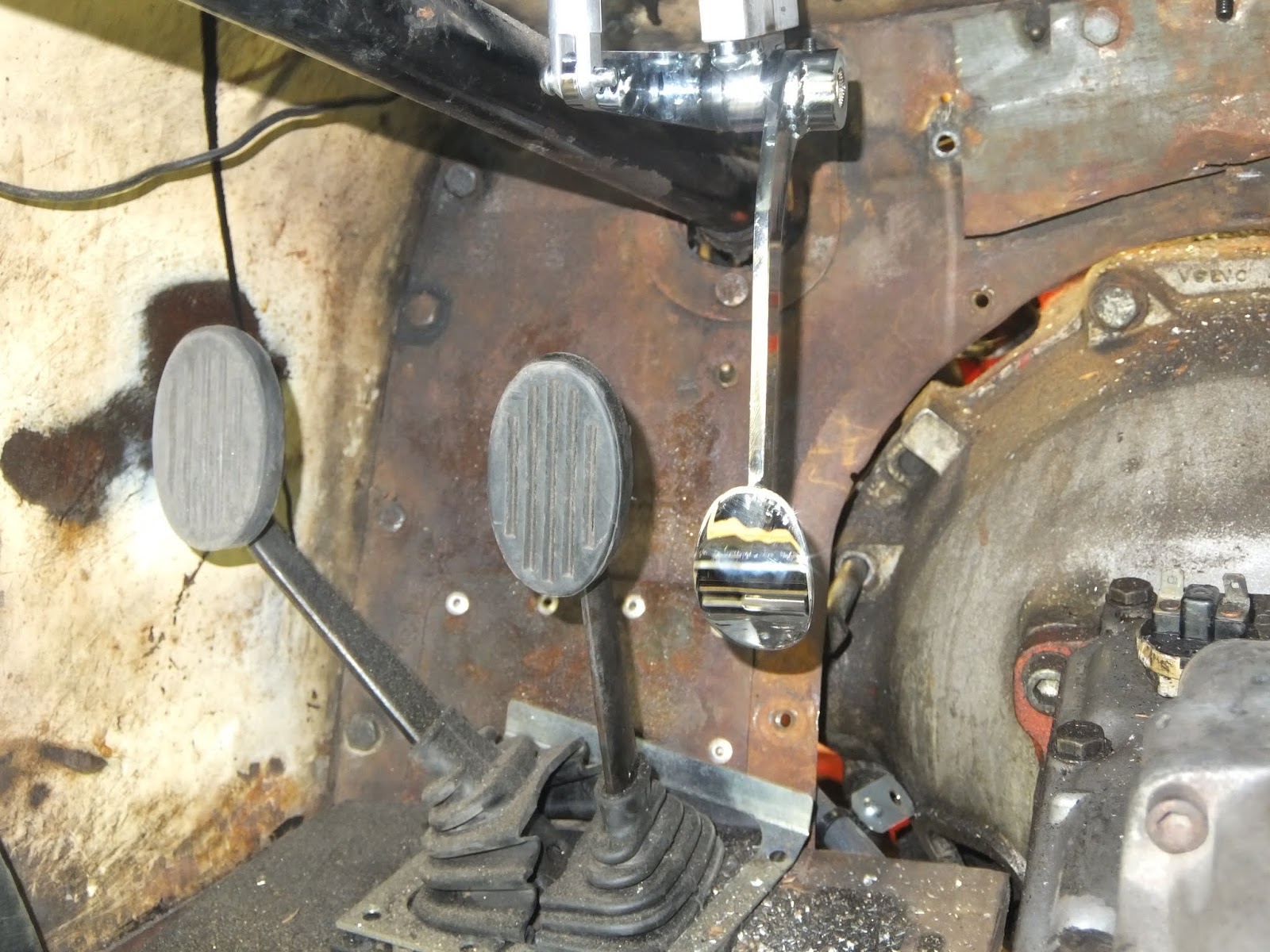
However, I later realized that much of the problem was because I added heat shielding, carpet and a thick floor mat to Beck's floor. Before, there was nothing but bare floor, and the pedal cleared. With the carpet in place, It was bottoming out well before the full travel.
Look at this photo of the stock MG linkage (modified long ago at the engine end to adapt to the Volvo linkage):
At the engine end, the travel was constrained by the design to about 1.25", not quite enough to reach full throttle even without the carpet. To achieve that, the pedal end has to move through an arc of nearly 6 inches! Even worse, the movement felt like "down" instead of "forward." I kept getting cramps in my ankle from using it. I resolved to convert to a modern "quadrant" cable assembly, emboldened by a great article I found on Grassroots Motorsports:
As proof of concept, I made a circular quadrant from aluminum and used it to measure how far the cable would need to move. It was exactly 1.5". Volvo experts will notice that I borrowed the special washer that holds the throttle spring to have a place to attach my cable.
With that determined, using the lathe and milling machine I made a more durable quadrant of steel, with a groove to hold the cable, four set screws to attach to the throttle linkage, and a through hole for the cable end (the "pill"):
Next up: figure out a pedal and cable assembly, and for that I turned to the aftermarket industry that serves hot rodders. This complete setup from eBay merchant
Hot Rod Parts Supply only cost about 38 bucks including shipping:
The only problem is that the pedal was designed to mount to a vertical firewall like in a T-bucket, and the engine end had the adapter to hook up to a modern four-barrel carburetor. I made a fancy custom pedal mount that also manages the cable attachment, designed to mount to the bottom of the battery tray under the dash:
After mounting, here's the way the pedals sit. Excuse the mess - this is a work in progress!
I also needed to make a bracket for the engine end of the cable, and a bit of drilling, bending and painting on a piece of flat steel accomplished that. Incidentally, a digital angle gauge was very handy in getting the angled bend from the flat mount on the first try:
Following the instructions that came with the kit, I shortened the braided cable sleeve and installed it, and then could measure the cable for length and cut it. All that was left was creating the "pill" on the end of the cable. I found a
YouTube video that had a crazy fixture to make it, and I duplicated that and added the cable end:
When done, it looked just like the video!
Time for a test, and... the pill popped right off. Multiple other tests with the cut-off end of the cable yielded similar results. Whatever that cable is made of, the solder would just not adhere to it. Back to the drawing board. After some deliberation, I decided that opposing set screws could trap the cable in a hole drilled down into the body of the quadrant. Here is that modification:
I later realized that I had just re-invented the same solution that the kit manufacturer used to hold the cable in the unused four-barrel carb linkage. I also realized this will be
much better if I need to disassemble the cable to adjust or maintain it.
I put it all back together, and it works great! Full throttle, no binding, no slippage. Here's what the engine linkage looks like:
This was admittedly a complicated project, but I just love this sort of shade-tree engineering, especially when the result is so good. I have probably 15 hours in this, but now it's done and ready to work well when I get a working engine in there. And that will be pretty soon, I hope. I'm meeting Joe Lazenby in two days from this writing to check out a used engine. I hope to use that this summer while building a strong and reliable permanent replacement!
Continue on to Part 40...


Nice work. I ended up TIG welding to make the Pill. That works if the cable material is weldable.
ReplyDeleteThanks for that feedback, Steve! Currently I have MIG, but not TIG. Someday...
Delete