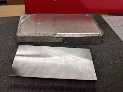
Part 2 starts with milling the metal for the base. In the photo below, I started with a rough chunk of aluminum like the one at the rear. I bought several of them at the last Cabin Fever expo, and paid next to nothing for them. As you can see, some CNC machining left the top very uneven, and the edges and bottom weren't much better. In the front, the finished base:
To get that off the ground, I started by rough cutting to shape in the bandsaw, locking the metal down in the Un-vise:
Machining metal is definitely a hobby for the patient, especially using the light hobby-grade equipment I have. It took me about two hours to get from the rough piece in the first photo to the finished one. Then, I needed to use another piece (thankfully, closer to size and shape) to get the uprights. Some drilling and tapping, and the base and uprights were under way:
I love my Digital Readout on the mill, because it makes aligning the holes pretty straightforward:
In this view, you can see to the left what the assembled frame looked like, and how I countersunk the holes for the socket head cap screws on the right.
Of course, the plan didn't call for square uprights like that. The designer specified angled sides to make it look better, and also to provide another machining challenge:
There are a couple of way to accomplish that, and I decided to try both, just for the experience. First, I had to reacquaint myself with the basics of trigonometry. Here's a useful diagram from mathisfun.com:
Actually, even before doing that, I started drawing a diagram, based on the dimensions I knew from the plan. I computed the Hypotenuse, because I managed to remember the Pythagorean Theorem for that. It's an old joke, with the punch line, "The squaw of the hippopotamus is the sum of the squaws of the other two hides."
I used the sine to compute the angle, but of course, I could have used the tangent without even computing the hypotenuse. I did that and got the same answer.
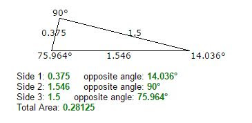
Just to be double-sure, I also used the site calculator.net to check my results:
Once I had all that figured out, I marked out the workpieces based on the measurements in the drawing. It's hard to get that exactly right, but it would let me know if I was really wrong. I took this picture after milling the first one:
To accomplish that, I used a digital angle gauge to set the angle to 14 degrees based on my previous calculations:
I double-checked against my scribed line using a ruler divided into 100 divisions per inch (I had to use a magnifying glass to see it), and was within about 0.025". Good enough. I started milling.
As I mentioned, there are two ways to do this, and for the other upright, I tried the other one. First, I used the horizontal bandsaw to trim the workpiece near the scribed line:
Of course, I could no longer use the angle gauge to align things, because the cut was not even nor square. Instead, I used that precise ruler to align the scribed line to the vise and milled away. I liked that method better anyway for this low-precision cut. It was a lot faster, and actually easier to tap into alignment without messing with the angle gauge. Once done, the match between the two pieces fell into the category of Plenty Good Enough As Long As You Don't Need It Exact. Here's the assembled base:
Next on the agenda for that is to disassemble, drill each piece to near the final dimension, and then reassemble and do the final boring.
The other progress has been on the flywheels. My friend Phil gifted me a couple of slices of bronze that will make very nice flywheels. The first step was to clean up the faces from the saw cut. The piece is large enough that I had to install the outside jaws for the chuck:
Once that was done, I measured them, and made both of them the same thickness as the smaller one. That turned out to be 0.605." That's good, because it adds mass over the nominal 1/2" specified. I just have to remember to make the crankshaft longer to compensate!
Turning the flywheels requires a holder called a mandrel, and that took some experimentation. I had bought some bearings on Amazon that had the nominal 1/4" diameter for the shaft, but when they came, a 1/4" piece of drill rod wouldn't begin to fit. Using pin gauges to measure, I realized the hole in the bearing was actually 0.249" - one thousandth less than 1/4". I had some other steel rod that measured that dimension, and they fit the bearings just fine.
So, I used that as a shaft in my mandrel, left slightly less than 1/2" as a shoulder, and threaded the front 1/4-20. I bored the mandrel 0.250" (luckily, I had the right reamer), and used permanent Loctite to bond it together. Since that part will be subjected to some torque, I also drilled and inserted a brass pin through the shaft to keep it from breaking loose. You can see all of that in this final picture:
Next up is to precisely bore the flywheels so I can install them on the mandrel for turning. I hope to use my Sherline lathe for that, just to see if it can handle it. Phil told me I could have more bronze if I messed these pieces up, but I hope to avoid going back to the well...
This project is taking a lot of time! I had hoped to finish before July 22nd (today is July 5th), when Phil and I are doing another library demo for Make717. We'll see!


Good progress. Isn't it fun to drag the old trig stuff out? I remember thinking in high school "I'll never use this", foolish youngster that I was.
ReplyDelete