
Then, I found the same phone mount on a suction cup base, and it was cheap - only about 4 bucks shipped from China. Of course, it took a few weeks to get here, but it did arrive:

It looked very promising, but there were two immediate problems:
1. There was no place in my BMW Z4 that was big enough and flat enough for the suction cup to work.
2. Even on a perfect surface like glass, the suction cup failed after a few hours, dropping the mount to the floor. I was testing without the phone in place, so I'm sure it would have dropped even faster with the weight of the phone!
So, I decided to use all this machinery I have to make something that merged this mount with a likely mounting point in the car. I found a screw location at the bottom of the ashtray that seemed promising. I'll start with this unfortunately blurry photo of the mount, and then describe how I made it:

You can't see it, but there's a countersunk screw hole running down the length of the aluminum shaft - that's what holds it firmly to the car.
To get started, I used my new-to-me lathe and magnificent tailstock drill chuck to center drill the aluminum with a bit sized to the eventual #8 screw that would hold the whole unit in place:

Then, I turned a couple of inches down just a touch, to make it shiny.

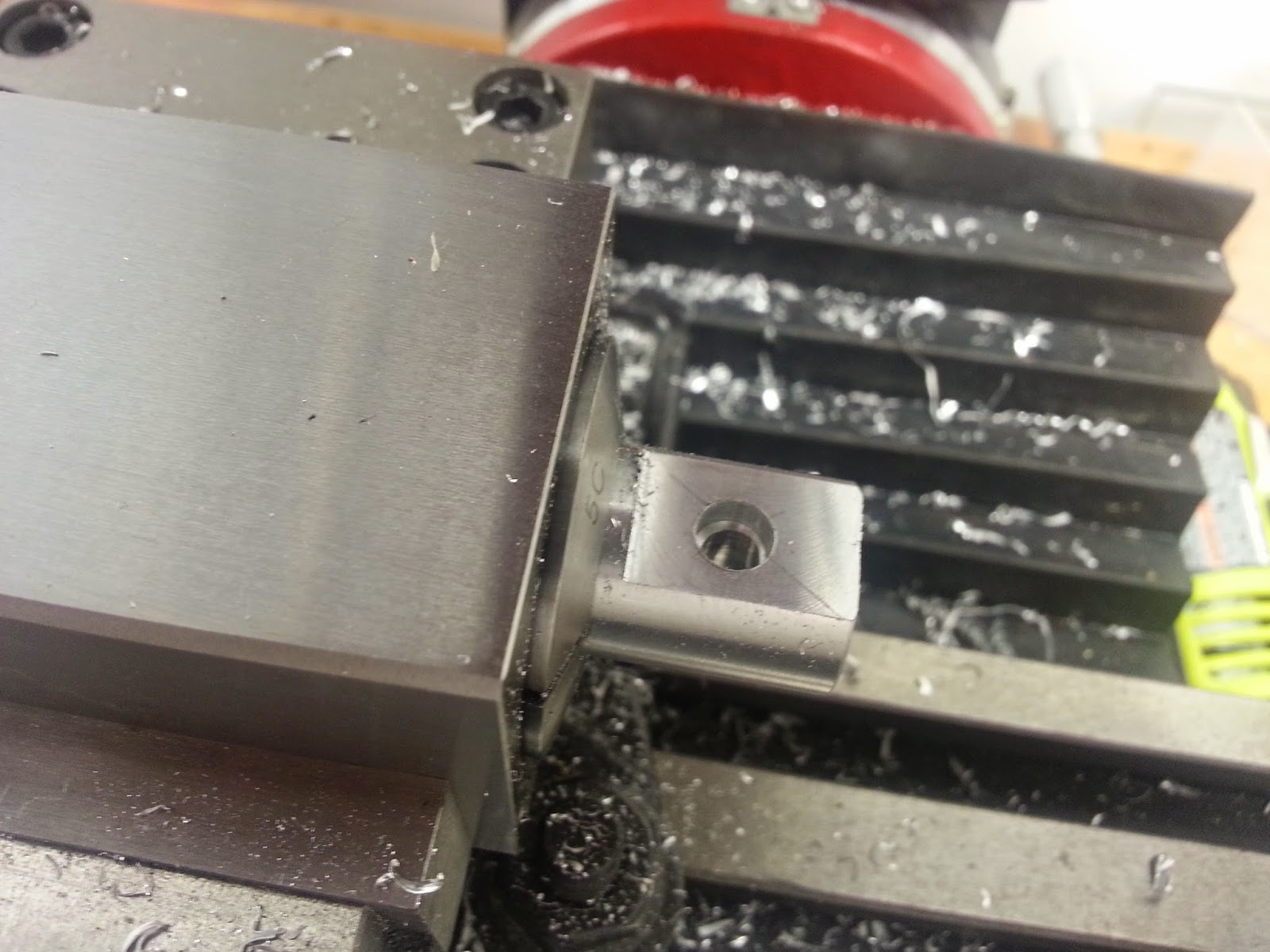
After cutting that part off and facing the cut end smooth, I mounted it in a device called a collet block. This is designed to hold it tightly, while allowing it to be held in a vise at a very precise angle and location. Once there, I put it in my mill vise, and milled a flat on one side, 0.100" deep.

After marking the location for the locking screw, I located it with my center finder, and then drilled it straight through with a number 7 drill bit - that's the right size to be tapped for 1/4-20 later. Before moving it, I also drilled a 0.150" countersink with a letter F drill - that's the "tight" clearance hole spec for 1/4-20.

The next step was to orient the piece to mill the slot to hold the adjustable arm. My setup is not the best, but I was able to temporarily clamp a machinist's square in place, and use that to square the collet block to the vise and mill spindle:

Next was a cool toy called an electronic edge finder - it lights up at the instant it touches the collet block. Because the tip has a precise diameter, and the collet block has a precise width, a little math will let you move the mill to the exact center of the workpiece. I double-checked with a rod turned to a point, to see if it aligned with the center of the rod:


Perfect! Except that was when I noticed that I had put the block in the vise with the hole facing me. It should have been 90 degrees around. I took it apart and did it over. Finally it was ready to mill the slot. Milling with at 3/8 cutter, and then taking a bare 0.006 off one side, matched the measurements I had made:

That picture makes it look like I plowed a huge slot through, but with my little mill and my tenuous workholding arrangement, I could only take 0.015" at a pass. It took nearly 50 passes to cut that slot! The wider side is for the tapped hole for the mounting screw. the thinner side was supposed to flex a bit to lock it, but I could have made it thinner yet.
Before removing the work from the collet block, there was one more operation to do - tap the threads for the mounting screw. I started the threading from the mill chuck to keep the threads square, and then finished it by hand:

A little cleanup with a file, and then some fitting on the plastic arm, and it all went together. Mounting in the car was fiddly, because I had to mount the aluminium post first, and then assemble the mount to it in a kind of tight space.

I snapped the faceplate on the mount, and it was good to go - everything fit, and I could still reach all the buttons, and it didn't interfere with the shifter:

I usually take my blog photos with my cell phone, which posed a problem here - the phone couldn't take a picture of itself! I had to go home and dig out an "old-fashioned" digital camera for the final beauty shot, which also shows how nicely the adjacent power plug and a short cable provide power to the phone:

Honestly, that shot is a little misleading, because it was made in my garage. Out in the sun with the top down, the phone screen is pretty washed out. But it is plenty good enough to use as a GPS. We have a road trip planned for early summer, and this will be a treat. I will probably add an aux audio input to the stereo so I can also use it to play music stored on the phone and via Pandora and other streaming services.
Now I need to do a similar project for my Z3 Coupe. I bought two of those mounts for exactly that reason!
Nice bit of machining. You've got all the right tools for it.
ReplyDelete